
How to Test an Oxygen Sensor With an OBD2 Scanner

Quick Answer
To test an oxygen sensor with an OBD2 scanner, connect the scanner, read stored and pending trouble codes, warm the engine, and monitor oxygen sensor live data. A conventional upstream narrowband sensor typically switches between approximately 0.1 and 0.9 volts during normal closed-loop operation, while a downstream sensor often shows a steadier signal. Compare the readings with fuel trims and manufacturer specifications before deciding whether the sensor has failed.
Steps to Check an Oxygen Sensor
- Read the codes: Record stored, pending, and relevant permanent diagnostic trouble codes before clearing anything.
- Warm the engine: Check that the engine reaches normal operating temperature and enters closed-loop fuel control.
- Open live data: Select oxygen sensor voltage, air-fuel ratio or lambda data, fuel trims, and loop status when available.
- Watch the signal: Look for appropriate changes rather than judging the sensor from one voltage reading.
- Compare sensors: Evaluate upstream and downstream readings according to their different roles.
- Confirm the cause: Check wiring, connectors, exhaust leaks, fuel mixture problems, and sensor heater faults before replacing parts.
Important Diagnostic Tip
- The familiar 0.1–0.9-volt switching test applies to conventional narrowband sensors, not every modern wideband air-fuel ratio sensor.
- Use the vehicle manufacturer’s specifications to confirm borderline or unusual readings.
An OBD2 scanner can help you check an oxygen sensor without removing it from the exhaust. The trick is knowing which sensor you’re testing and how its live data should behave.
I’ll explain how to read sensor signals, interpret trouble codes, compare fuel trims, and recognize faults that can look like a bad sensor. These checks can help you narrow down the cause before spending money on replacement parts.
In This Guide
What Does an Oxygen Sensor Test Check?
An oxygen sensor test checks whether the sensor reports exhaust oxygen conditions correctly and responds as the engine management system expects. The results can help identify a sensor fault, a wiring problem, or an air-fuel mixture issue.
What is an oxygen sensor?
An oxygen sensor, also called an O2 sensor, measures oxygen in the exhaust and sends information to the engine control module (ECM). The computer uses this information to help regulate the air-fuel mixture and monitor catalytic converter performance.
Many gasoline vehicles have sensors both before and after the catalytic converter. Their locations and functions matter when interpreting scan-tool readings.
- Bank 1 Sensor 1 (B1S1): The upstream sensor before the catalytic converter on the engine bank containing cylinder number one.
- Bank 1 Sensor 2 (B1S2): The downstream sensor after the catalytic converter on that bank.
- Bank 2 sensors: Additional sensors on the opposite cylinder bank when the engine and emissions system use them.
Sensor numbering can vary with the vehicle’s exhaust layout, so check the manufacturer’s service information if you’re unsure which component you’re viewing.
Why test the sensor instead of replacing it immediately?
A trouble code involving an oxygen sensor doesn’t automatically prove that the sensor itself has failed. The same warning can result from damaged wiring, an exhaust leak, a heater-circuit fault, or a mixture problem elsewhere in the engine.
For example, a lean-condition code may appear when unmetered air enters the intake. Replacing the oxygen sensor without checking that possibility could leave the original fault unresolved.
**Section takeaway:** Identify the correct sensor and understand its job before interpreting any voltage or diagnostic code.
What Do You Need Before Testing?
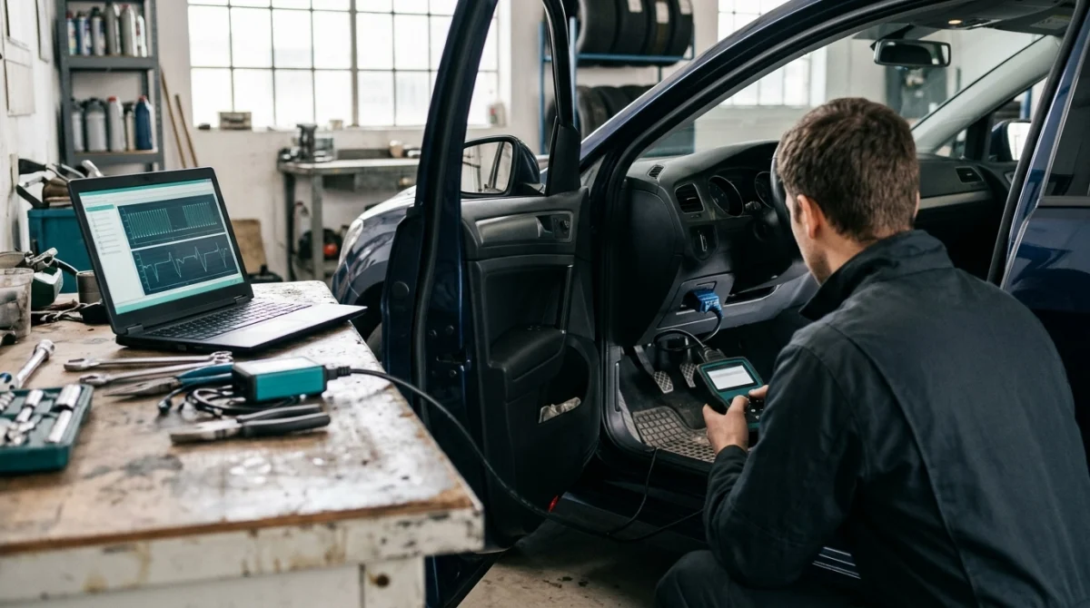
You need an OBD2 scanner with live-data capability for the most useful non-invasive test. A basic code reader may identify a fault code but won’t necessarily show the sensor’s changing signal.
Choose a scanner that displays live data
Look for a scanner that supports the following parameters when your vehicle makes them available:
- Oxygen sensor voltage or sensor signal.
- Air-fuel ratio or lambda readings for wideband sensors.
- Short-term fuel trim (STFT) and long-term fuel trim (LTFT).
- Closed-loop or open-loop status.
- Engine coolant temperature and engine speed.
- Oxygen sensor heater status or onboard monitor test results, if supported.
A scanner with graphing can make sensor behavior easier to evaluate than rapidly changing numbers. Enhanced manufacturer-specific data may also be necessary for certain vehicles.
Prepare the vehicle safely
Park on a level surface in a well-ventilated area, select Park or Neutral as appropriate, and apply the parking brake. Keep hands, cables, and clothing away from moving belts, fans, and hot exhaust parts.
Follow the vehicle’s service instructions before running engine tests. Never work beneath a vehicle supported only by a jack, and don’t conduct a road test while watching a handheld scanner.
Technician’s note: Exhaust components become extremely hot, and exhaust gases can be dangerous in enclosed spaces. Stop if you notice a strong exhaust leak, fuel leak, or other immediate safety concern.
How to Test an Oxygen Sensor Step by Step
Use the scanner to check the fault codes first, then evaluate live data with the engine at the correct operating temperature. This sequence helps you separate a sensor’s behavior from the conditions that influence its signal.
Step 1: Connect the OBD2 scanner
Locate the vehicle’s diagnostic connector, usually beneath the dashboard. Connect the scanner and switch the ignition on as directed by the tool; start the engine only when the test calls for it.
Step 2: Read and record trouble codes
Open the diagnostic trouble code menu and record all stored and pending codes. Save freeze-frame information when available, because it captures operating conditions associated with a detected fault.
Common oxygen-sensor-related code groups include:
- P0130–P0135: Examples of Bank 1 Sensor 1 circuit, signal, and heater-related faults.
- P0136–P0141: Examples of Bank 1 Sensor 2 circuit, signal, and heater-related faults.
- P0150–P0161: Related circuit and heater code families that can apply to Bank 2 sensors.
- P0171 and P0174: Lean-mixture codes that may involve causes other than the oxygen sensors.
Exact code definitions and applicability depend on the vehicle. Don’t clear the codes before recording them, as doing so can erase useful diagnostic information and reset emissions-monitor readiness.
Step 3: Warm the engine and confirm closed-loop operation
Start the engine and let it reach the operating conditions specified by the manufacturer. Check the scanner’s loop-status parameter when available.
During closed-loop operation, the computer uses feedback from the relevant sensors to adjust fueling. A conventional upstream narrowband oxygen sensor generally becomes easier to assess after the sensor and engine have warmed up.
A cold engine, an inactive sensor heater, or open-loop operation can make an otherwise functional sensor appear inactive. Don’t condemn a sensor based on a cold-start reading alone.
Step 4: Select the correct sensor data
Open the live-data menu and choose the upstream sensor you want to examine. Select its voltage or other appropriate signal, then add STFT, LTFT, engine speed, and loop status when possible.
Graph the signal if your scanner supports it. If the vehicle uses a wideband air-fuel ratio sensor, choose the appropriate lambda or equivalence-ratio data instead of assuming its signal follows the traditional narrowband voltage pattern.
Step 5: Observe the signal over time
Watch the readings for enough time to see a meaningful pattern under stable operating conditions. On a conventional narrowband upstream sensor, a signal that moves repeatedly between lean-side and rich-side voltage levels is generally expected during closed-loop operation.
Don’t expect every vehicle to behave identically. Engine strategy, sensor type, operating conditions, and manufacturer specifications all affect the expected response.
Step 6: Compare upstream and downstream behavior
Check the downstream sensor after the catalytic converter under the same suitable operating conditions. With a functioning catalyst, its signal often changes less rapidly than the upstream narrowband signal.
If both traces appear nearly identical, investigate catalytic converter efficiency and other possible causes rather than automatically blaming the downstream sensor. A graph alone cannot confirm a failed catalytic converter or oxygen sensor.
Section takeaway: A useful OBD2 test combines codes, warm-engine live data, operating status, and comparison between related readings.
How to Read Oxygen Sensor Live Data
The correct interpretation depends on whether your vehicle uses a narrowband oxygen sensor or a wideband air-fuel ratio sensor. The familiar voltage ranges apply to many conventional narrowband sensors, but they aren’t universal specifications.
What voltage should an upstream oxygen sensor show?
A conventional zirconia narrowband upstream sensor typically switches between approximately 0.1 volts and 0.9 volts during warm, closed-loop operation. Lower voltage generally indicates a lean exhaust condition, while higher voltage generally indicates a rich condition.
The important clue is the pattern, not a single reading. A signal that remains fixed at one extreme may indicate a fault, but the engine’s actual mixture, wiring, and sensor operating conditions must also be checked.
| Live-data pattern | Possible interpretation | What to check next |
|---|---|---|
| Upstream narrowband signal switches between low and high voltage | Often normal during closed-loop operation | Compare response and fuel trims with vehicle specifications. |
| Signal stays near the low end | Lean mixture, wiring fault, or sensor problem | Check fuel trims, intake leaks, exhaust leaks, and circuit condition. |
| Signal stays near the high end | Rich mixture, signal-circuit fault, or sensor problem | Check fueling, wiring, and manufacturer diagnostic procedures. |
| Signal changes slowly or appears sluggish | Possible aging sensor, contamination, or other operating fault | Check response under appropriate conditions and inspect related systems. |
| Downstream signal is relatively steady | Often consistent with normal catalyst monitoring | Compare against the upstream trace and the vehicle’s specifications. |
How do you recognize a slow oxygen sensor?
A slow sensor may eventually reach both rich and lean readings but take longer than expected to respond. This differs from a sensor that produces no usable signal at all.
Use graphing or supported response-time tests to assess the signal. A scan tool’s update rate can make a rapidly changing sensor look slower than it really is, so confirm suspicious results with suitable diagnostic equipment.
What if your car has a wideband sensor?
Many newer vehicles use wideband air-fuel ratio sensors, especially for upstream mixture control. These sensors can provide more detailed mixture information than conventional narrowband sensors.
Your scanner might display lambda, equivalence ratio, current, or a manufacturer-specific value instead of a simple 0.1–0.9-volt signal. A lambda value near 1.0 generally represents the chemically balanced air-fuel mixture for the fuel being burned.
Don’t apply narrowband voltage rules to a wideband sensor’s displayed data. Use the correct PID description and the manufacturer’s expected ranges.
Section takeaway: Read the sensor type before judging its numbers, and investigate abnormal patterns instead of treating one reading as proof of failure.
How to Interpret Trouble Codes and Fuel Trims
Oxygen sensor codes tell you which circuit or monitoring function detected a problem, while fuel trims help show how the engine computer is correcting the mixture. Reading both together often gives a clearer diagnostic direction than either one alone.
What do STFT and LTFT tell you?
Short-term fuel trim (STFT) reflects relatively immediate fuel corrections, while long-term fuel trim (LTFT) reflects learned adjustments over time. Positive values generally mean the computer is adding fuel, and negative values mean it’s subtracting fuel.
Values near zero are often desirable, but normal readings depend on the vehicle and operating conditions. A small fluctuation doesn’t establish a fault, and there isn’t one universal acceptable trim range for every engine.
For example, consistently positive trims alongside a lean-looking upstream signal may point toward a lean mixture. Potential causes include an intake vacuum leak, inadequate fuel delivery, an exhaust leak ahead of the sensor, or a sensor problem.
How do you distinguish a bad sensor from a mixture problem?
Use the overall pattern rather than replacing the part named in a code. The following examples illustrate where to investigate next.
- Lean code with positive trims: Look for unmetered air, fuel-delivery problems, or exhaust leaks that can distort sensor readings.
- Rich code or strongly negative trims: Investigate excessive fueling, leaking injectors, fuel-pressure problems, or other causes of a rich mixture.
- Heater-circuit code: Check the heater’s power supply, ground or control circuit, wiring, and sensor heater according to the service procedure.
- No-activity or slow-response code: Confirm the sensor receives the conditions it needs to operate, then check its signal and circuit.
- Repeated catalyst-efficiency code: Compare upstream and downstream behavior and investigate catalyst performance, exhaust leaks, and related faults.
These are diagnostic directions, not definitive conclusions. Several faults can produce similar readings, and a sensor may be inaccurate without setting a clear circuit code.
What does Mode 6 tell you?
Some scanners can retrieve onboard monitor test results through Mode 6 or a related diagnostic menu. These results may help evaluate supported oxygen sensor or emissions-system tests against the vehicle computer’s thresholds.
Availability, test identifiers, and result formats vary by vehicle and scanner. A completed test that passes doesn’t necessarily rule out an intermittent problem, and an unsupported test doesn’t mean the sensor has failed.
Diagnostic tip: Record the original codes, freeze-frame data, fuel trims, and sensor traces before clearing codes or disconnecting components. Those details can help a technician reproduce the problem.
Section takeaway: Combine oxygen sensor data with fuel trims and fault codes to narrow down the cause before buying a replacement sensor.
When Should You Replace the Sensor?

Consider replacement when testing confirms that the sensor fails to meet the manufacturer’s specifications and its wiring, heater circuit, and operating conditions have been checked. A trouble code by itself isn’t enough evidence.
Signs that deserve further testing
These symptoms can accompany oxygen sensor problems, but none is exclusive to a failed sensor:
- A check-engine light with a relevant oxygen sensor or heater code.
- Fuel economy that has worsened without another clear explanation.
- Rough running, hesitation, or unusual mixture-related behavior.
- Repeated emissions-test problems.
- Live data that remains abnormal after engine warm-up and initial circuit checks.
Before replacing anything, inspect accessible wiring and connectors for corrosion, heat damage, or loose connections. Also consider exhaust leaks, misfires, fuel-system problems, and sensor contamination where appropriate.
Can you test the sensor without replacing it?
Yes. A live-data test is a useful first check because you can observe the sensor while it’s installed and operating in the vehicle.
However, some problems require more than a generic OBD2 scanner. A digital multimeter, oscilloscope, manufacturer-specific diagnostic tool, or additional mechanical testing may be needed to verify a suspected fault.
When should you ask a professional?
Seek qualified diagnostic help when readings conflict, a wideband sensor’s data is unclear, a heater or wiring fault needs electrical testing, or the vehicle has persistent drivability problems. Professional testing can help avoid replacing good parts while the real problem remains.
Technician’s note: Follow the vehicle-specific service manual when testing circuits or replacing an oxygen sensor. Never apply power or ground to unidentified sensor wires, as incorrect connections can damage the sensor or engine computer.
Section takeaway: Replace a sensor after confirming the fault, not simply because a code mentions oxygen sensor performance.
Frequently Asked Questions
Can I test an oxygen sensor with a basic OBD2 scanner?
Yes, if the scanner supports live data for the relevant sensor. You can often read codes and view available sensor values, but advanced functions such as graphing, manufacturer-specific parameters, or Mode 6 may require a more capable tool.
What voltage should an oxygen sensor show at idle?
A conventional narrowband upstream sensor often switches between approximately 0.1 and 0.9 volts at warm idle in closed-loop operation. Downstream sensors and wideband sensors behave differently, so use the appropriate specifications for your vehicle.
Does an oxygen sensor code always mean the sensor is bad?
No. A code can point to a heater circuit, damaged wiring, an exhaust leak, or an air-fuel mixture problem. Diagnose the cause using live data and the manufacturer’s test procedure before replacing the sensor.
Can an OBD2 scanner identify a bad catalytic converter?
A scanner can help identify possible catalyst-efficiency problems by displaying relevant codes and comparing upstream and downstream sensor behavior. However, those readings alone may not confirm converter failure; other faults must be ruled out.
Should I test the oxygen sensor with a cold engine?
A cold-start check can reveal some electrical or heater-related information, but it isn’t the best condition for judging normal oxygen sensor switching. Warm the engine according to the manufacturer’s instructions and confirm closed-loop status before evaluating normal operating behavior.
Can I drive with a faulty oxygen sensor?
It depends on the fault and the vehicle’s symptoms. A faulty sensor can affect fuel control and emissions, and a flashing check-engine light or severe misfire warrants prompt attention. Stop driving if the vehicle shows serious symptoms or an immediate safety concern.
Final Takeaway
Testing an oxygen sensor with an OBD2 scanner starts with reading trouble codes, warming the engine, and examining the correct live-data parameters. The best diagnosis comes from combining sensor behavior with fuel trims, heater status, wiring checks, and manufacturer specifications.
Don’t replace a sensor based on one unusual number. Confirm the operating conditions, rule out related faults, and use a qualified technician when the results remain unclear.
